Introduction: Reference and Protocol Models and Layered Architectures
A reference model is a non-implementation specific foundation that provides a clear understanding of the functions and processes necessary for consistent nonproprietary protocol development. The OSI reference model satisfies this definition since it provides a set of standards to ensure networking compatibility and interoperability and serves as a guideline for protocol design and instruction. The OSI reference model generically describes the communications process and therefore does not regulate it as manufacturers may create products that combine functions of one or more layers.
In contrast, a protocol model closely matches the structure of a protocol suite and may in fact be defined by the protocol suite’s implementation. As an example, the TCP/IP protocol model describes the communication process and functions at each layer of the Internet standard TCP/IP protocol suite.
A layered architecture facilitates development in complex environments by grouping specific related functions into separate well-defined layers with clear interfaces. This methodology reduces complexity by breaking the problem space into smaller and simpler components and standardizes interfaces facilitating multi-vendor development and modular component-based engineering. Layered architectures in conjunction with open standards define a common vocabulary necessary for understanding and cooperation in multi-vendor environments and positively results in increased competition and innovation. The architecture’s layers may also be called the architecture’s stack and these two terms will be used interchangeably. It should be noted that an architecture provides a blueprint that guides not only how the components are constructed but also when in the process they are designed, implemented, maintained and replaced.
OSI Reference Model Introduction
With the networking basis established above and on the Networking and Internet introductory page, we may now introduce the OSI reference model as an abstract, seven layer network architecture released in 1984 by the Organization for Standardization (ISO). A very elemental description of OSI communications consists of a message source (e.g. users, devices and processes), a communications medium, and a message destination (e.g. users, devices and processes). For illustration consider the following use-case example:
The communication process begins at the source application layer where data is generated and passed down the reference model’s stack (i.e. down through the 7 layers), transmitted across a medium and received by the destination where it is passed up the reference model’s stack (i.e. up through the 7 layers) to the destination application. Particularly important, note that equivalent or peer layer protocols at the source, destination and intermediary devices collaborate by adding, interpreting or removing encapsulated control information thereby providing transparent communications to the layers above them. Please come back and read this example after you have finished reading this page as it will make more sense.
The preceding introductory OSI communications example subsumes an understanding of packet-switched communications technology. A packet switched architecture breaks or segments application messages into small blocks of data known as Protocol Data Units (PDU). These PDUs are called different names depending on the layer and this naming architecture will be introduced below. PDUs travel independently and can take different dynamic routes to their destination thereby realizing an adaptable communications methodology. This creates an environment that does not require an active connection or rely on a single circuit for service reliability.
Segmentation also provides a mechanism to increase network efficiency through time-division multiplexing however note that segmentation also increases complexity and incurs processing overhead decreasing effective throughput. Note that data segmentation is not to be confused with network segmentation.
OSI Reference Model Details
The OSI reference model defines a layered network architecture where communication begins at the source application layer and data is sequentially passed down the architecture’s layers, possibly broken up, encapsulated at each layer (encapsulated by adding header and trailer information as illustrated in Figure 1 below), transmitted across a medium and then passed up the destination architecture’s layers where it is progressively decapsulated (i.e. headers and trailers are stripped off and the messages are reconstituted). Inherent in this architecture is the understanding that peer levels communicate with each other (e.g. source and destination application layers, source and destination presentation layers, etc.).
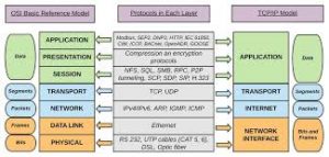
Before proceeding further, the OSI model defines the following seven layers listed and described from the top layer to the bottom layer: (a) the application layer provides users and application level processes with an interface to underlying networking functionality, (b) the presentation layer encapsulates the application data and ensures application layer data is readable on other systems, (c) the session layer encapsulates presentation layer data and creates and maintains conversations (i.e. dialogues) between source and destination applications, (d) the transport layer encapsulates session data in application addressed segments (e.g. ports) and is responsible for overall end-to-end transfer of data, (e) the network layer encapsulates transport layer segments in logically addressed packets and provides services to exchange packets over a network between end devices, (f) the data link layer encapsulates packets in physically addressed frames and places frames on and takes frames off each medium, and (g) the physical layer responsible for data transmission therefore defining the physical components, the encoding and the signaling. This architecture provides the mechanism for peer level communication.
Prior to discussing the individual layers in detail, it is worth reemphasizing that the application data is segmented, encapsulated in PDUs, passed down the source’s stack and serially transmitted to the destination as a bit stream. Upon reaching the destination, the bit stream is retrieved from the medium, reconstructed into PDUs, de-encapsulated and reconstructed as it is passed up the stack. In this model, each layer adds, interprets or removes information created and used by peer layers (e.g. source network layer protocols communicates with destination and intermediary device’s network layer protocols). Also note that the adjacency sequence above identifies the layer’s interfaces (e.g. the network layer interfaces with the transport layer above and the data link layer below). It is also worth reinforcing that network addressing takes place at three different layers in OSI model as follows: (a) transport layer PDUs known as segments or datagrams contain the destination and source process or port numbers, (b) network layer PDUs known as packets contain the destination and source logical addresses and, (c) data link layer PDUs known as frames contain destination and source physical addresses. The three upper OSI layers (Application, Presentation and Session) process, interpret or render application data while the physical layer adds timing and synchronization information to the serialized PDUs. To simplify our analysis of the architecture’s layers below we will describe the encapsulation functionality from the top layer to the bottom however the reader can easily deduce the reflexive decapsulation functionality moving from the bottom layer to the top layer.
OSI Application Layer Functionality
Applications are software programs used by people or services. The OSI application layer provides users and application level processes with an interface to underlying networking functionality. In this capacity, the application layer provides a communication service that provides protocols to exchange data between peer programs running on source and destination hosts. At the source, the application layer serves as the first component to prepare human understandable data for transmission on data network. At the destination, the application layer receives data from the lower layers and prepares it for human use. It must be noted that a single application can employ many different application layer services and that many applications may exist concurrently on a single end system.
OSI Presentation Layer Functionality
The OSI presentation layer may best be described from a historical perspective. Early computer networks carried character-based information or data. Today’s networks have evolved into a converged telecommunications infrastructure that not only carries data but also carries voice and many forms of multimedia. While discussed in further detail below, the TCP/IP protocol model evolved quicker and prior to the emergence of the OSI model, converged telecommunications and the personal computer (PC) revolution and therefore combines the OSI presentation and session layers with its application layer.
The OSI model designers foresaw the need to create a separate layer to handle different and unforeseen encodings thereby assisting with the presentation of application data. With this basis, the OSI presentation layer is responsible for three primary functions: (a) coding and conversion of application data, (b) compression and decompression of data at source and destination to improve communications throughput, and (c) encryption and decryption of data at source and destination to ensure security. Examples of emergent presentation layer formats accommodated by the OSI presentation layer include Apple’s QuickTime and the Motion Picture Experts Group (MPEG) video formats and the Joint Photographic Experts Group (JPEG), Tagged Image File Format (TIFF) and Graphics Interchange Format (GIF) image formats and the Secure Sockets Layer (SSL).
While this will be presented again below, consider Secure HTTP or HTTP Secure (e.g. https). Secure HTTP uses OSI Presentation Layer SSL/TSL to provide bi-directional encryption of OSI Application Layer HTTP. In the TCP/IP model SSL/TLS (Secure Sockets Layer/Transport Layer Security) is a TCP/IP Application Layer sublayer operating beneath the TCP/IP Application Layer HTTP.
OSI Session Layer Functionality
The OSI session layer was designed to maintain conversations between source and destination applications. This includes the necessary functionality to initiate, maintain and restart conversations. This session layer functionality provides for efficient data transfer, classes of service and exception reporting. In this capacity the session layer provides the architecture to synchronize communication between presentation and application layers on source and destination hosts.
OSI Transport Layer Functionality
As introduced above, the transport layer is the uppermost layer to deal with addressing by establishing, maintaining and terminating virtual circuits. With this basis the transport layer provides a link between the top three layers that handle data on the “application level” and the lower layers that handle the specifics of networking. This illuminates a critical component and benefit of the OSI and TCP/IP layered models since applications can transparently access networking functionality without knowing the specific details of the underlying network. With this basis the transport layer supports the upper layers with the transparent transfer of data between systems.
The transport layer encapsulates application data in segments and is responsible for overall end-to-end transfer of application data. It must be reinforced that the transport layer receives this application data stream from the session layer above which in turn received it from the presentation layer. The transport layer provides the functionality for multiple applications on a single device to access the communication network at the same time and if required, provides reliable data reception in the correct order to upper layers.
As cited above, we have recently observed the convergence of all forms of communications (e.g. voice, video and data) through a common data communications platform. This has increased the complexity of data communications citing that different data streams have varying data requirements. As an example, some data requires complete or reliable reception in order to be useful (e.g. e-mail, Web pages, business transaction data, etc.) while in some instances, incomplete data may still be acceptable (e.g. video streaming and VOIP). Similarly, some data can accept reasonable delays to ensure reliable delivery while some real time data needs to be received as quickly as possible. To meet these specific implementation needs, mechanisms or protocols are required to accommodate both reliable and unreliable functionality. We will see below that the TCP/IP protocol model accommodates both of these situations.
The transport layer segments and encapsulates the data stream by breaking the data stream up into segments. This segment encapsulation adds a header that contains addressing and control information to support reliability. Transport layer addressing is comprised of source and destination port numbers that identify specific application layer processes or services running on the end hosts. Server-side port numbers tend to be predefined so they may be commonly known in advance and found by clients whereas client side port numbers tend to be generated randomly to increase security. Transport layer control information includes the information necessary to create, maintain and terminate a conversation and provide reliable communications if required. The amount of header information necessary depends on whether the connection requires a connection oriented and reliable or unreliable communications. Unreliable connectionless communications requires less control information and therefore incurs a lower processing and transmission overhead. Reliable data communications requires control data to create a dialog (e.g. through a three-way handshake), track and acknowledge transmitted data and retransmit unacknowledged data.
In summary, the transport layer: (a) tracks individual communications between source and destination applications, (b) segments data and manages each segment, (c) reassembles segments into streams of application data since PDUs can take different routes and arrive out of order, (d) performs flow control adjusting to network congestion to prevent and recover from the loss of segments, and (e) provides error recovery through the retransmission of segments.
OSI Network Layer Functionality
The OSI network layer, commonly referred to as layer three was designed to: (a) provide services to exchange packets over a network between end devices, (b) provide media independent logical addressing to achieve end to end packet transport, and (c) provide connectionless, unreliable or best effort transport that results in desired low overhead. The OSI network layer accomplishes these design goals by providing functionality that can be grouped into the following four general tasks: (a) addressing packets with logical source and destination IP addresses, (b) encapsulating transport layer segments into layer three packets for the lower data link layer, (c) routing IP packets from source to destination, and (c) decapsulating the packets when passing them up to the transport layer.
It should also be noted that intermediary devices may act on the packets. Intermediary layer three devices may receive the packets (passed up through the intermediary device’s stack), analyze the destination and select the next hop in the packet’s path. This layer three communications processing continues until the packets reach the end device’s directly connected network.
OSI Data Link Functionality
The data link layer commonly referred to as layer two provides a means to exchange data over local media by encapsulating packets in frames and placing frames on and taking frames off each medium. The reference model’s separate layered functionality serves a critical purpose in this regard as the upper levels do not need to concern themselves with the communication channel’s physical addressing or the characteristics of a specific medium. The data link layer is independently responsible for determining the timing, encoding, error detection, access methods and Maximum Transmission Unit (MTU) relevant for the particular medium. Similar to layer three intermediary devices, layer two intermediary devices may analyze and re-encapsulate frames according to their physical media (e.g. copper, fiber optic or wave), access methods (e.g. serial or contention) and topology (i.e. the arrangement of nodes and their connections). This reference model architecture provides a resilient future-proof approach as the architecture can accommodate and transparently integrate emergent and unforeseen communications technologies. This reference model definition also serves to clearly distinguish a reference model from a protocol model. The layer two protocol model is determined by the actual protocols that depend on the network topology and the technology used to implement the topology. It should be noted the topology and technology is driven by the size, cost and necessary services of the network.
As introduced above, a layer two PDU is called a frame and includes a header, data and a trailer. Similar to the layer three PDU, the layer two PDU header contains control information that among other things includes the source and destination physical addressing. The layer two data contains the layer three packet and the trailer contains additional control information in the form of a Frame Check Sequence (FCS) that is most commonly a Cyclic Redundancy Check (CRC). The FCS’s purpose is to determine whether errors occurred during transmission or upon reception. To accomplish this, a CRC is generated at source and encoded in the frame’s trailer. When the frame arrives at the destination, a CRC is regenerated and compared with CRC generated at the source and located in the frame’s trailer. If the CRCs match, the frame is accepted, if the CRCs do not match the frame is discarded. It should be noted the CRC provides error detection and should not confused with reliability or error correction
OSI Physical Layer Functionality
The OSI physical layer commonly referred to as layer one is responsible for data transmission and addresses the fundamental principles of data communications that includes the physical components, the encoding and the signaling. The physical layer’s delivery of frames requires four elements as follows: (a) the physical media and their associated connectors, (b) the representation of data on media, (c) the encoding of data and control information, and (c) the transmission and reception circuitry on network devices. A component of the physical layer’s design is to minimize the effects of overhead and interference citing that media may be shared by traffic from many protocols and is subject to physical distortions. The physical layer is also responsible for timing as devices need to know where a sequence or signal begins and ends through the use of synchronization bits. It should be noted that the OSI physical layer is different from other OSI layers in that it is largely hardware-based and was designed by communications engineers in contrast to the upper layers that were designed primarily by software engineers. From an implementation standpoint and similar to layer two, layer one must also consider the appropriate media in terms of application effectiveness, cost, bandwidth and throughput.
References
Brown, K., Craig , G., Hester , G., Stinehour, R., Pitt, W. D., Weitzel, M., Amsden, J., Jakab, P. M., & Berg, D. (2003). Enterprise java programming with IBM WebSphere. Boston MA: Pearson Education
Caudle K., & Cannon, K. (2004). CCNA: Guide to Cisco networking (3rd ed.). Boston, MA: Course Technology
Cetron, M. J., & Davies, O. (2008). Trends shaping tomorrow’s world: Forecasts and implications for business, government, and consumers (Part One). The Futurist, 42(2), 35-52.
Comer, D. E. (2000). Internetworking with TCP/IP: Principles, protocols and architectures, (4th ed.). Upper Saddle River, NY: Pearson Publishing.
Dye, M. A., McDonald, R., & Rufi, A. W. (2008). Network fundamentals: CCNA exploration companion guide. Indianapolis, IN: Cisco Press
Globalization—Why all the fuss?. (2008). In Britannica Book of the Year, 2001. Retrieved February 13, 2008, from Encyclopedia Britannica Online: http://search.eb.com/eb/article-9344646
Friedman, T. L. (2005). The world is flat: A brief history of the 21st century. NY: Farrar, Straus and Giroux
Laudon, K. C., & Laudon, J. P. (2004). Management information systems (8th ed.). Upper Saddle River, NY: Pearson Publishing.
McQuerry, S. (2004). CCNA Self-Study: Interconnecting Cisco network devices (INTRO) 640811, 640-801. Indianapolis, IN: Cisco Press
McQuerry, S. (2008). CCNA Self-Study: Introduction to Cisco networking technologies Part 1 (ICND1) 640-822 (2nd ed.). Indianapolis, IN: Cisco Press
Odom, Wendell (2003). CCNA INTRO exam certification guide (CCNA Self-Study, 640-821, 640-801), (1st ed.). Indianapolis, IN: Cisco Press
Pearlson, K. E., & Saunders, C. S. (2006). Managing and using information systems (3rd ed.). Hoboken,NY: Wiley Publishing.
Rainer, R. K., Turban, E., & Potter, R. E. (2007). Introduction to information systems. Hoboken, NJ: Wiley Publishing.
Satinger, J. W., Jackson, R. B., & Burd, S. D. (2002). Systems analysis and design (2nd ed.). Boston, MA: Course Technology