Introduction
This page will present the Star, Extended Star, Ring and Mesh networking topologies. As previously presented, a network architecture is a conceptual blueprint that determines the physical and logical network and intuitively includes the network topology and protocols. Network architectures must be designed to appropriately balance the organizational and end device’s needs and these considerations include: (a) the speed or data rate, (b) the cost of the components, their installation, and their maintenance, (c) the necessary fault tolerance, (d) the network’s scalability, (e) Quality of Service (QOS), (f) security, and (g) availability. These considerations have a direct correlation with the choice of both the network topology and the use of the appropriate transport layer protocol.
Networking Topologies
A topology is generically defined as a geometric configuration defined by a set of points. Extending this broad definition, we define a networking topology as the layout of devices and their interconnections. This definition accommodates our discussion of both physical and logical networking topologies. Note that the physical and logical topologies may be the same or they may be different. A network’s physical topology is defined by the geometric arrangement of nodes and their connections and includes primary and backup connectivity, intermediary network devices, and end systems. The physical topology depends on and must match the type of communication medium. The network’s logical topology is defined by the paths data signals take through the physical topology and therefore define virtual circuits. Note the virtual circuit is not to be confused with connection oriented circuit-switching as this presentation assumes an TCP/IP infrastructure based on connectionless packet-switching as introduced in previous presentations.
Referencing the previous OSI and TCP/IP architecture presentation, recall that layer two protocols are determined by the technology used to implement a particular topology. In accord with the architectural design considerations cited above, note that the networking technology is determined by the network’s size and the network service requirements. With this basis, different categories of connections and networks can be distinguished based on their geography and requisite services. First, from a geographical basis we can distinguish between Local Area Networks (LAN) and Wide Area Networks (WAN). LANs typically use high bandwidth technology capable of supporting a number of local hosts. WAN architectures connect systems across greater geographical distances and therefore must accommodate more extreme environmental factors. With this basis, it is obvious that LANs and WANS will have different architectural and topological considerations.
Continuing our foundational basis, we may distinguish between point-to-point and multi-access topologies. A physical point-to-point topology connects two nodes directly and therefore allows the data link MAC protocols to be very simple since frames can only travel between the two nodes (e.g. WANs). In a point-to-point architecture, frames are placed on the communications medium at the source and removed at the destination. Note that a logical point-to-point topology may include a number of intermediary devices. In a logical point-to-point connection, a virtual circuit is transparently established between geographically separated end devices.
Conversely, multi-access topologies are characterized by a number of nodes using shared media to communicate. In a multi-access environment, data is placed on the shared communications medium and every node on the medium sees all frames. This requires careful design and methods to regulate transmission manage access and minimize collisions (e.g. CSMA/CD and CSMA/CA). Multi-access topologies also incur increased overhead as every device is required to parse and inspect the frame’s header to determine its destination.
Lastly, data communications can be distinguished as simplex where data flows in one direction only, half duplex where data flows in one direction at a time, or full-duplex where data travels in each direction simultaneously. Again, note that simplex, half-duplex, and full-duplex can be defined both physically and logically.
Linear Bus Topology
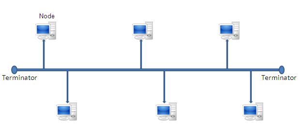
The Linear Bus is a multi-access topology where all devices connect to or tap into a single common backbone. This results in a contention-based environment where all devices broadcast their messages on the backbone and all frames are visible to all devices on the bus backbone. This multi-access shared medium requires protocols to manage transmissions in an effort to maximize throughput. The Carrier Sense, Multiple Access with Collision Detect (CSMA/CD) protocol is a good example of the requisite management protocols and will be discussed in Ethernet and CSMA/CD. The ability for every device to read all frames introduces security concerns. The bus is also susceptible to a single point of failure and therefore suffers from availability concerns.
The bus is a relatively simple and inexpensive implementation requiring minimal administration if designed and implemented according to best practices (e.g. adhering to maximum cable length constraints, limiting the number of users based on their transmission requirements, etc.). The ends of the backbone cable must be properly terminated to ensure the signal is absorbed rather than being reflected back as this will seriously hamper communications. Network designers can extend the bus topology through the use of layer one hubs also known as multiport repeaters. Hubs can enhance a network’s resiliency as a centralized device and dedicated cables can overcome single points of failure. It must be noted that layer one devices do not parse or process frames and therefore do not logically segment collision domains.
When hubs are used to connect linear buses the result is tree topology. Tree topologies allow organizations to add network segments incrementally and cost-effectively as they can use equipment from multiple vendors. Intermediary network devices perform processing and therefore incur transmission latencies. Increased network latencies increase the chance of communications collisions and therefore render the network susceptible to a storm of frame collisions and retransmissions. When implementing a tree topology using layer one devices, network designers are advised to adhere to the de facto standard “5-4-3” rule that provides constraints on data communications. The “5-4-3” rule states that a network should be constrained to never permit the separation of any two nodes on a network by more than five segments, four repeaters, or three backbone segments.
The industry has also seen the tree topology extended to connect with layer two star topologies. If implemented correctly, a tree topology implemented with layer two devices may cost-effectively overcome some of the broadcast domain limitations of the bus technology. While still in use today, the bus topology has largely been replaced by star topologies that rely on layer two switches and wireless (Wi-Fi) technologies. It should be noted Wi-Fi also implements a multi-access communications medium however Wi-Fi manages communications through the Carrier Sense, Multiple Access with Collision Avoidance (CSMA/CA) protocol.
Star and Extended Star Topologies
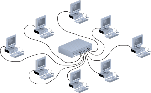
The layer two star and extended star topologies are the most common physical topologies in LANs today since they can implement contention-free networks that optimize throughput. In contrast to the bus topology, LAN devices are added to the network by connecting them point-to-point to a central network device. This central device is responsible for controlling all communications within the star.
This central networking device is most commonly a switch however star topologies can also be created using a layer one hub or even a layer three broadband modem/router/wireless access point (WAP) as they are in many homes. Note that it is the router that facilitates the creation of a star topology in the home as a WAP is a multi-access contention-based architecture and requires CSMA/CA protocols.
While the use of a central connection point allows each end device to have a dedicated cable to the central device, stars are more expensive than bus implementations since they require substantially more cabling and a central networking device. The star cabling configuration overcomes the resiliency shortcoming of the bus as it is not susceptible to a single point of network failure however if the central device fails, the entire system will fail. An extended star topology is a hierarchical design often seen in WANs and enterprise or campus LANs. In this environment, the extended star consists of a central device that connects both computers and other network devices and therefore creates inter-networks.
Ring Topology
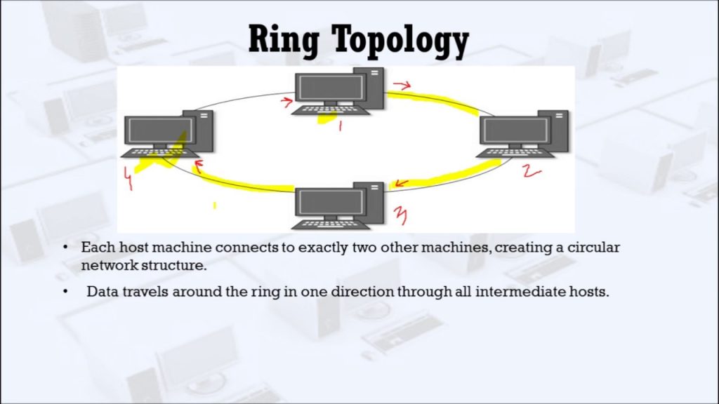
The ring topology connects all devices, point-to-point in a circle and this can be either a physical topology, logical topology, or both. This results in devices having exactly two neighbors and similar to the bus topology, all devices along a communications path read and analyze the frame to determine if they are the intended recipient. This intuitively introduces security concerns similar to the linear bus. Also similar to the bus topology, a physical ring is susceptible to a single point of failure however this can be overcome through the use of a redundant second ring or bypass functionality. Physical rings do not require end terminators since there is no beginning or end and they support various access methods.
Today, the ring topology’s predominant access method is through the use of Token Ring protocols introduced by IBM in 1984. The Token Ring has since been adopted and maintained by IEEE 802.5 specification (IEEE, 1998). The IEEE 802.5 specifies medium access is granted through a token travels around the ring allowing devices to transmit when they possess the token (IEEE, 1998). This results in a contention-free environment that provides guaranteed or deterministic bandwidth to all devices. The Token Ring adds complexity and overhead since provisions must be made to prevent a station from monopolizing the medium. Additionally, provisions must be established to generate a new token if the token is lost. This requires that one station undertake token administration or alternatively, token administration can be done through distributed albeit even more complex token management.
Rings require additional processing and technical requirements associated with synchronization. In a typical ring, data moves from point to point and requires the signals to be repeated and resynchronized at each station. This may be accomplished through centralized management or by obtaining clock information from the incoming signal. Due to distortions in the signal, a clock recovery error known as timing jitter will be increasingly introduced into the system. Timing jitter is cumulative around the ring and thus limits the number of repeaters, the size of the ring, and the number of stations the network may contain. In a fiber-optic system jitter is minimized due to the low distortion of optical transmissions.
One implementation of the Token Ring is the Fiber Distributed Data Interface (FDDI) which employs dual, fiber optic, counter-rotating rings (presented in physical media). Evidence of the Token Ring’s resiliency can be ascertained from its implementation to support the requisite real-time processing constraints of the Freedom Space Station. An FDDI network is configured as 2 independent, active, counter-rotating rings allowing multiple configurations using one or both rings. This redundancy enables the network to dynamically reconfigure when failures are detected however FDDI also specifies hardware to bypass inoperative nodes further enhancing its real-time processing support capabilities. FDDI also specifies both synchronous and asynchronous communications however a full discourse on the FDDI is beyond the scope of this presentation.
Mesh and Partial Mesh Topologies
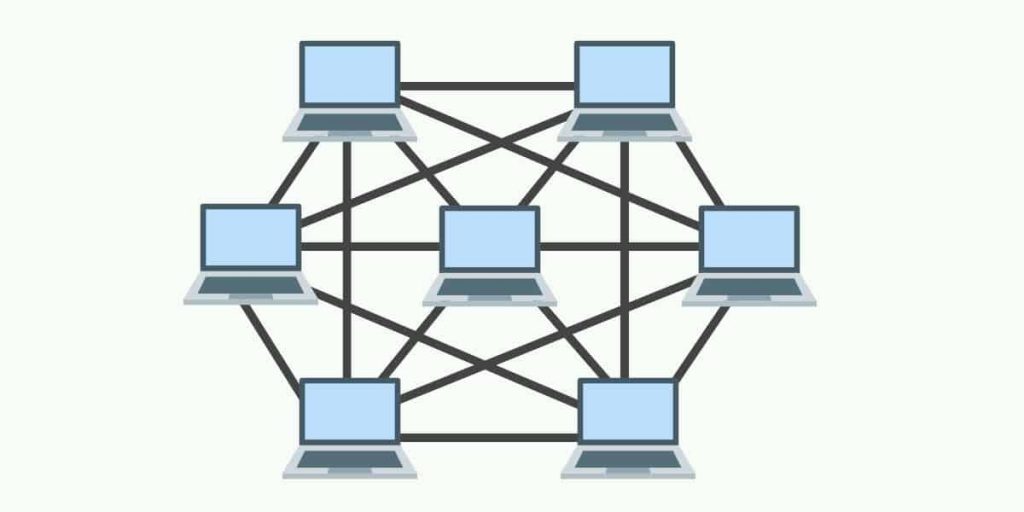
The mesh and partial mesh topologies provide redundant physical and logical connections between devices and therefore facilitate dynamic routing. Dynamic routing allows the network to adapt to congestion and failure by providing multiple paths between source and destination. Providing multiple or redundant paths can overcome single points of failure thereby increasing the network’s resiliency and availability. Note that a mesh topology also increases the complexity of network management as intermediary devices must run routing and switching algorithms to calculate and maintain paths. The classic example of a mesh topology is today’s Internet. A partial mesh is defined as a network where at least one device maintains multiple connections to all other devices. A full mesh is defined to represent a network where all devices are connected to one another and this is expensive to implement.
Summary and Perspective
As previously introduced, network architectures must be designed to appropriately balance the organizational and end device’s needs and these considerations include: (a) the speed or data rate, (b) the cost of the components, their installation, and their maintenance, (c) the necessary fault tolerance, (d) the network’s scalability, (e) Quality of Service (QOS), (f) security, and (g) availability. These considerations have a direct correlation with the choice of both the network topology and the use of the appropriate transport layer protocol (presented in next lesson). The topologies discussed above provide designers with a myriad of flexible choices to meet their organizational communications needs. Network designers must also understand that bandwidth is consumed by media access strategies (e.g. token protocols), control frames, headers, virtual circuits, faults, and acknowledgments. It must be strongly asserted that network implementation choices be in concert with an organization’s business goals as Return on Investment (ROI) and Total Cost of Ownership (TCO) are imperative tenets to maintaining a competitive advantage in the present economic climate.
References
5-4-3 rule (2009). Pcmag.com encyclopedia. Retrieved April 9, 2009, from http://www.pcmag.com/encyclopedia_term/0,2542,t=5-4-3+rule&i=37141,00.asp#
Caudle K., & Cannon, K. (2004). CCNA: Guide to Cisco networking (3rd ed.). Boston, MA: Course Technology
Comer, D. E. (2000). Internetworking with TCP/IP: Principles, protocols and architectures, (4th ed.). Upper Saddle River, NY: Pearson Publishing.
Dye, M. A., McDonald, R., & Rufi, A. W. (2008). Network fundamentals: CCNA exploration companion guide. Indianapolis, IN: Cisco Press
Erl, T. (2005) Service-oriented architecture: Concepts, technology, and design. Upper Saddle River, NJ: Pearson Education
Friedman, T. L. (2005). The world is flat: A brief history of the 21st century. NY: Farrar, Straus and Giroux
Graham, S. Davis, D. Simeonov, S. Daniels, G. Brittenham, P. Nakamura, Y, Fremantle, P. Konig, D., & Zentner, C. (2005). Building Web services with Java (2nd ed.). Indianapolis, IN: Sams Publishing
IANA. (2002). RFC 1700. Retrieved April 13, 2009, from http://www.iana.org/assignments/table-of-contents
IEEE. (1998). IEEE 802.5: LAN/MAN Token-Ring access method. Retrieved April 11, 2009, from http://standards.ieee.org/getieee802/802.5.html
IETF. (1980) RFC 768 User datagram protocol. Retrieved April 11, 2009, http://www.ietf.org/rfc/rfc768.txt
IETF. (1981) RFC 793 Transmission control protocol: DARPA Internet program protocol specification. Retrieved April 11, 2009, from http://www.ietf.org/rfc/rfc0793.txt
Jain, R. (1990). Performance analysis of FDDI token ring networks: effect of parameters and guidelines for setting TTRT. ACM SIGCOMM Computer Communication Review 20(4), 264 – 274.
Johnson, M. J. (1987). Proof that timing requirements of the FDDI Token Ring protocol are satisfied. IEEE Transactions on Communications, 35(6), 275 – 286.
Kamoun, F. (2007). The convergence of business process management and service oriented architecture. Retrieved June 9, 2008 from the Association of Computing Machinery: http://www.acm.org/ubiquity/views/v8i24_bmpsoa.html
Laudon, K. C., & Laudon, J. P. (2004). Management information systems (8th ed.). Upper Saddle River, NY: Pearson Publishing.
McQuery, S. (2008). CCNA Self-Study: Introduction to Cisco networking technologies Part 1 (ICND1) 640-822 (2nd ed.). Indianapolis, IN: Cisco Press
Pearlson, K. E., & Saunders, C. S. (2006). Managing and using information systems (3rd ed.). Hoboken,NY: Wiley Publishing.
Porter, M. (1985). Competitive advantage: Creating and sustaining superior performance. New York: The Free Press
Ross, F. E. (1989). An overview of FDDI: the fiber distributed data interface. IEEE Journal on Selected Areas in Communications, 7(7), 1043 – 1051.
Satinger, J. W., Jackson, R. B., & Burd, S. D., (2002). Systems analysis and design (2nd ed.). Boston, MA: Course Technology
Shpilberg, D., Berez, S., Puryear, R., & Shah, S. (2007). Avoiding the alignment trap in information technology. MIT Sloan Management Review 49(1).
topology. (2009). In Merriam-Webster Online Dictionary. Retrieved April 3, 2009, from http://www.merriam-webster.com/dictionary/topology
Verity, B. (2003). Guide to networking cabling fundamentals. Boston, MA: Course Technology