Introduction
This page will present the three types of physical layer network media used in data communications and their strengths and weaknesses. The three basic types of physical layer media to be presented are (a) copper cable, (b) fiber optic cable, and (c) wireless technologies. The general properties of copper cable as a data communications medium will be discussed followed by the individual analysis of coaxial, unshielded twisted pair (UTP) and shielded twisted pair (STP). The analysis of fiber optic cable will include a brief discussion of the Fiber Distributed Data Interface (FDDI) as it serves as a representative example. To reasonably limit the length of this presentation, discussion of wireless technologies will be constrained to the Institute of Electrical and Electronic Engineers (IEEE) 802.11 Wireless LAN standard. This will exclude IEEE 802.16 WiMAX (Worldwide Interoperability for Microwave Access) Local Area Network (LAN) technologies, IEEE 802.15 Wireless Personal Area Networks (i.e. Bluetooth WPAN), and cellular Global System for Mobile Communication) (GSM).
Background
It is well known that interconnections have historically been a limiting factor in computing power and speed. The physical layer network media is the foundation of any network and provides the framework for the network architecture. Choosing and implementing the correct and appropriate type of cable is critical to data communications and therefore an organization’s success.
A critical component of today’s converged communications is scalability citing the debilitating cost of obsolescence as organizations rely on data communications to remain competitive. With this basis, a network’s physical media and its inherent bandwidth can be a limiting factor to an organization’s communication needs and business goals. Network designers must consider throughput, cost, size, scalability, connectors, and immunities to environmental factors when designing their systems.
As stridently asserted throughout this course, business needs must drive IT design and implementation and cost is a critical factor in today’s business climate. Network designers must assess not only the cost of the medium but also the cost of the end and intermediary communication devices include the network interface cards (NIC), hubs, switches, and repeaters. Furthermore, network designers must not only consider the cost of network installation and management but they must also understand the maintenance phase is the most expensive phase of the System Development Life Cycle (SDLC). It is critical that organizations draw on industry best practices and perform the proper systems analysis and design prior to network implementation. Fortunately, network designers can draw from standardized structured cabling best practices that have quickly matured over the last 20 years.
Structured Cabling
In 1984, the deregulation of the telecommunications industry began with the divestiture of AT&T. Following this deregulation, many companies sought to design, install, and maintain telephone systems and provide their services with a wide range of proprietary devices. Standardization of cabling systems began in 1985 when the Computer Communications Industry Association (CCIA), the American National Standards Institute (ANSI), the Electronics Industry Association (EIA), and its subgroup the Telecommunications Industry Association (TIA) began to develop cabling standards. Note that cabling standards development is more complex than the creation of the OSI and TCP/IP models since cabling best practices are developed not only through consensus but they must also adhere to government codes and regulations. The end result of this initiative is the ANSI/EIA/TIA-568 Commercial Building Wiring Standard (CBWS) which is now is responsible for specifying standards-based structured cabling in the U.S.
The goal of structured cabling is to present a standard, enterprise-wide, multivendor cabling infrastructure that is cost-effective, maximizes performance, and minimizes maintenance. A clearly defined, standards-based, structured cabling architecture is critical citing that different types of physical media must be blended to form a cost-effective, flexible, scalable, and resilient enterprise communications architecture. The ANSI/EIA/TIA-568 CBWS provides network administrators with a blueprint that guides their technology deployment in specific instances.
Concisely summarized, a standards-based structured cabling architecture: (a) provides a consistent, scalable, and converged architecture that can use the same physical layer media for data, voice, and video, (b) supports the integration of multivendor equipment, (c) simplifies management, (d) supports the ability move users and devices, (e) simplifies troubleshooting, and (f) supports new applications with minimal upgrade difficulties. The ANSI/EIA/TIA-568a Commercial Building Wiring Standard provides specifications and guidance to network engineers by defining six subsystems or layers of on-premises infrastructure as follows: (a) the entrance facility where telecommunications services enter a building, (b) equipment rooms that contain the telecommunications equipment common to all building occupants and include the telephone system’s private branch exchange (PBX), servers and mainframes, (c) telecommunications closets that provide common access points to the backbone, (d) backbone pathways that may also connect buildings, (e) horizontal pathways that connect workstations to the transmissions media, and lastly (f) the work area, were occupants use telecommunications devices. It is obvious connecting these subsystems will require a mix of physical layer media to meet cost-effective organizational communications needs.
Also critical to telecommunications cable and equipment installation is grounding and bonding. Grounding and bonding are driven by applicable government and industry codes and standards that provide safety to personnel and directly affect system stability and information assurance. A detailed discussion of grounding and bonding as well as the physics of how electrical signals are amplified and transmitted over the physical communications media is beyond the scope of this presentation.
Physical Layer Background
As a basis, data transmissions can be distinguished between analog and digital transmissions. Analog signals are continuous electromagnetic signals characterized by variable voltages whereas digital signals are discrete and directly represent encoded digital logic. It should be noted that analog electromagnetic digital signals are often determined within a specified range whereas digital fiber-optic signals are far more precise. Bandwidth is a measure of the difference between the lowest and highest frequencies a media can transmit and is expressed in hertz (Hz). Higher frequencies can transmit more data in a given period of time since they accommodate more transitions. Throughput is defined to be the amount of effective data that a network can accommodate during a given time and is usually measured in megabits per second (Mbps). Throughput is determined by the physical nature of the media, the network’s physical and logical configuration, and the network’s management protocols. Lastly, it should be noted that network analysis and queueing theory has shown that the full utilization of a network’s bandwidth will never be realized. As network traffic increases, the individual waiting times increase according to an exponential curve and ultimately result in unacceptable delays or even the collapse of the network.
Network designers must remain cognizant of the environment and the physical medium’s susceptibility to electromagnetic interference (EMI) and radio frequency interference (RFI). As a basis, inducing a current in a conductor creates EMI, and reflexively, inducing or changing a magnetic field can induce a current in a conductor. EMI is created by electrical devices and cables that create electromagnetic fields and can, therefore, induce currents in other electrical conductors. Examples of devices that create EMI include all forms of electronics, power lines, and fluorescent lights. Consider that fluorescent lights may be used throughout a building and many network implementations use the crawlspace above a drop-down ceiling to run their network cables adjacent to their fluorescent lights. RFI may be created incidentally by electrical devices or intentionally by broadcast signals. Examples of RFI-creating devices include microwave ovens, wireless phones, Bluetooth devices, and baby monitors.
Copper Cable
Consistent with our design tenets introduced above, the choice of a communications medium must necessarily assess the business needs in relation to the medium’s throughput, bandwidth, cost, size, scalability, connectors, and immunities to environmental factors. The communications industry had a similar choice when developing electrical conduction-based communications cables. The choice of a conducting medium is a compromise of the material’s electrical resistance, resiliency to corrosion, cost, weight, and strength and copper satisfies this compromise. Consider that silver has less resistance and is a better conductor than copper and gold is less corrosive than copper but silver and copper are both significantly more expensive. Copper seems to have the best range of properties evidenced by its de facto adopted status.
As a basis, electrons are charged particles and therefore influence one another as well as being influenced by outside factors such as EMI and RFI. Typical network implementations use conduits of adjacent copper cables and this generates EMI and RFI and can result in crosstalk. Crosstalk is defined as noise or interference induced by adjacent electromagnetic cables. In addition to crosstalk’s ability to introduce noise in a system, crosstalk also allows communications to be read from adjacent media thereby creating a security concern.
Data communications using a copper-based medium require that digital signals be encoded as electromagnetic charges and transmitted as a current of electrons on the copper medium. There are many electro-magnetic encoding mechanisms and a full discourse on electromagnetic signal encoding is beyond the scope of this presentation. To provide a simple example of electromagnetic encoding, consider Ethernet’s use of Manchester encoding. Manchester Encoding uses a mid-cycle transition to indicate “0’s” and “1’s”. A mid-cycle transition from low voltage to high voltage indicates a “1” whereas a mid-cycle transition from high voltage to low voltage indicates a “0”. This mechanism embeds the clocking in the signal thereby accommodating timing jitter that results from the device’s clocking variations.
As previously introduced, today’s Ethernet can support a mix of speeds and mediums and this must be undertaken with adherence to structured cabling best practices. To be discussed below are the prevalent copper cable implementations in the United States, coaxial cable, UTP, STP, and a relative newcomer to the U.S. that enjoys wide deployment in Europe, screened twisted pair (ScTP). The analysis of copper cable will conclude with a brief introduction to two emergent technologies. The first emergent technology is Power over Ethernet which promises to significantly enhance flexibility, scalability and business agility. The second technology, Broadband Over Powerline has been in existence for some time but it appears to have regained momentum due to government funding.
Coaxial Cable
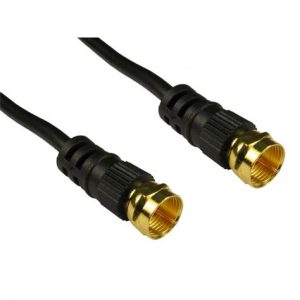
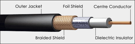
Coaxial cable is the foundation of Ethernet networks and cable television and comes in several types that share common construction. Coaxial cable consists of a central copper core surrounded by an insulator, a braided metal shielding and an outer sheath called the jacket. These three layers surrounding the copper core provide high immunity to EMI and RFI and facilitate coaxial cable’s relatively long maximum cable lengths. With respect to other communications cables to be discussed below (e.g. UTP and STP), coaxial cable is a relatively thick, heavy and inflexible cable and has therefore been superseded by newer technologies in many installations.
From a historical perspective, the original version 1.0 Ethernet specification used Thicknet or 10BASE5 coaxial backbone cable. To clarify the 10BASE5 nomenclature, the first number “10” refers to its data speed of 10 Mbps, the BASE refers to baseband meaning all of the cable’s bandwidth is used for each transmission, and the trailing “5” is shorthand for a 500-meter maximum cable length. As previously cited, the physical medium determines the network’s timing requirements and physical segment limitations (e.g. maximum length). 10BASE5 had strict implementation requirements as it had to be terminated by a 50 Ohm resistor and could only be tapped through the use of special vampire taps at specific intervals. Thicknet was superseded by 10BASE2 Thinnet which afforded easier installation but still required adherence to a strict connecting and tapping process using British Naval Connectors (BNC). BNCs required that technicians pay special attention to their connections as improperly connected BNCs resulted in network problems. Recall Ethernet’s contention-based environment did not facilitate easy troubleshooting thus an improperly connected BNC could seriously hamper network availability.
In contrast to the Ethernet’s coaxial baseband implementation, cable television uses coaxial cable for distributing broadband access the last kilometer to the home or business. In this environment, full-duplex internet traffic and hundreds of video signals are modulated into individual carriers and combined into a single broadband signal. On the customer premises, a cable modem demodulates the coaxial broadband signal and separates and directs the internet traffic to the computer’s Ethernet connection.
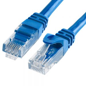
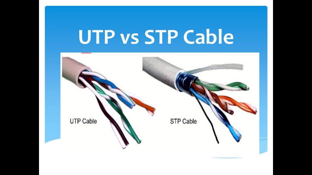
Unshielded Twisted Pair UTP and Shielded Twisted Pair
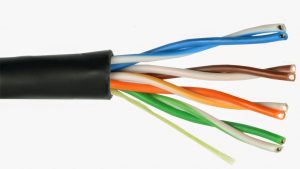
In 1984, IBM introduced the token ring architecture using thick shielded twisted pair cable capable of four Mbps data rates. Since that time, twisted pair has evolved to become the most frequently deployed communications medium in LANs today. There are presently three variants of twisted pair; Unshielded Twisted Pair (UTP), Shielded Twisted Pair (STP) and Screened Twisted Pair (ScTP) that is predominantly used in Europe. All three variants follow strict guidelines set by ANSI/EIA/TIA-568a. Note that twisted pair, while similar to traditional telephone cabling differs from telephone cabling in that it has an impedance of 100 ohms.
Common to all variants, the twisted pair consists of four color-coded pairs of plastic-insulated copper wire. Twisting wires in pairs serves to cancel their generated EMI and RFI and the number of twists per inch determines the wire pair’s grade. More twists per inch provides more resistance to all forms of noise however note that twisting the wires in pairs introduces propagation delays that will be skewed when using wires with different twist ratios. Lastly, four twisted wire pairs of different grades are then combined in a single wire that serves to further reduce crosstalk maximizing communications properties and therefore segment lengths. Four of the wires (two pairs) carry the positive voltage and the other two pairs carry the negative voltage. STP differs from UTP by surrounding the color-coded twisted pairs with a metallic shielding known as the foil. If the foil is properly grounded, the shielding acts as an antenna that converts noise into an opposite flowing current that further insulates the core from RFI and EMI.
UTP typically uses 22 or 24-gauge copper wire resulting in an external diameter of less than half a centimeter. This small external diameter in conjunction with UTP’s flexibility facilitates easy cable installation. A summary listing of UTP cable categories follows: (a) category one is used for telephone communications and is not suitable for transmitting data, (b) category two is capable of transmitting data at speeds up to 4 Mb per second, (c) category three is used in 10BASE-T networks and is capable transmission speeds up to 10 Mb per second, (d) category four is used in token ring networks and capable of transmission speeds up to 16 Mb per second, (e) category five is capable of transmitting data at speeds up to 100 Mb per second, (f) category five-e is used in networks running at speeds up to one gigabit per second (Gbps), and (g) category six consists of four pairs 24 gauge copper wires that can transmit data at speeds up to one Gbps. The primary UTP cables used in LAN environments today are categories five, 5e, and six citing that Fast Ethernet requires UTP category five or higher.
UTP and STP Connection Media
The last physical component of the physical layer is connection media which serves as an interface between devices and the physical media. NIC functionality was introduced earlier and will not be repeated. The most common connection of the NIC to the communications medium is with a registered jack (RJ) or RJ-45 where 45 refers to a physical connector with eight conductors. Similar to cabling specifications, UTP RJ-45 connector specifications are contained in the ANSI/EIA/TIA-568 standards. There are two different ways to attach the cable to the RJ-45 that depending on the devices that need to be connected. A straight-through cable uses either a T568A or a T568B at each end whereas a crossover or rollover cable uses a T568A at one end and a T568B at the other end. In general, connecting like devices is accomplished with a crossover cable (e.g. switch to switch, hub to hub, router to router, etc.), and different devices are connected using a straight-through cable (e.g. switch to desktop). Newer devices may utilize a Gigabit Interface Converter (GBIC) which is a hot-swappable device that plugs into a Gigabit Ethernet port and supports both copper UTP and fiber optic media.
Power over Ethernet (PoE) and Broadband-Over-Powerline (BPL)
Power over Ethernet (PoE) is an emergent technology analogous to Plain Old Telephone Service (POTS) allowing devices to receive power and data through the same cable. PoE uses existing Ethernet cabling and switching infrastructure to provide in-line power to external devices over a copper twisted-pair cable. PoE is an agile solution that allows organizations to add remote devices that need power without incurring the expense of adding and managing additional electrical cabling (e.g. VOIP phones, network-attached video cameras, wireless access points, and sensing devices). Similar to standards-based structured cabling and network reference models, the industry must quickly adopt a standards-based approach to ensure PoE development remains interoperable.
It appears that Broadband-Over-Powerline (BPL) has also regained some momentum due to increased federal government support. BPL is an attractive alternative to provide Internet access to rural areas where cable or digital subscriber line (DSL) implementation is not economically feasible. It is common for rural areas to possess the electrical grid infrastructure to support BPL access thus the implementation of BPL may be more cost-effective than deploying other technologies. BPL promises agile functional enhancements similar to PoE citing that using a single common carrier for data and power can facilitate automated remote sensing. An example of this cost-saving functionality is the ability to remotely read power meters.
Fiber Optic Cable
In the 1980s, the advent of distributed computing and high-speed peripherals required fast fault-tolerant communication beyond the capabilities of existing copper-based computer networks. As cited in the introduction, interconnections are a limiting factor in computer processing and one can assert this has been exacerbated citing that today’s distributed Web Services, Service-Oriented Architectures, and Grid Computing processing rely on fast fault-tolerant communications networks. It is no wonder that fiber optic cable, originally conceived as a backend network to connect high-speed storage devices in the 1970s has evolved to become a LAN/MAN alternative, the de facto standard in WAN telecommunications carrier,s and even a high-speed home Internet connection. Fiber optics is the natural evolution in cable-based networking since it offers increased bandwidth, greater noise immunity, low signal degradation and attenuation, chemical stability, flexibility, high security, and easy upgrading necessary for today’s converged communications infrastructure. To serve as a foundation, a brief comparison of electronic and photonic properties follows.
Electronic and Photonic Properties
Electrons are charged particles and thus influence one another as well as being influenced by outside factors. Photons, on the other hand, have no charge and may even pass through one another without interference theoretically supporting full-duplex functionality on a single optical fiber. Fiber optical bandwidth is several orders of magnitude greater than copper’s bandwidth and can be transmitted further than copper without signal regeneration. To provide a basis, optical fiber’s attenuation is rated at 2-5 dB/km compared to coaxial cables 50 – 200 dB/km rate. It should be noted that fiber-optic bandwidth is limited not by the fiber, but by the electronic devices that generate and detect the pulses of light. The inherent bandwidth of fiber is only limited by multimode dispersion caused by internal reflection within the fiber optic cable. Multimode dispersion lengthens the digital signals eventually rendering them unreadable by the receiver.
Fiber Optic Cable Construction
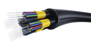
Fiber-optic cable consists of one or more glass or plastic optical fibers in its core that carry a photonic signal and the glass fibers are surrounded by a layer of glass called the cladding. The refractive index of the core is always greater than the refractive index of the cladding allowing the cladding to reflect light back into the core allowing the core to guide the signal along the cable. Functionally, the glass fibers carry the photonic signal, and the cladding acts as a mirror that reflects light back to the core enhancing its transmission characteristics. This internal reflection allows the fiber to bend around corners without diminishing the integrity of the signal. Fiber optic cables differ in their bend radius (i.e. ability to successfully carry transmissions around corners). Bends in the fiber optic cable increase reflection and refraction resulting in signal attenuation that limits the cable length. Note that imperfections in fiber optic cable result in signal absorption and also contribute to signal attenuation.
The fiber optic cable’s cladding is in turn covered by layers of plastic referred to as the buffer coating that provides ultra-violet, physical, and environmental protection. The buffer coating has two different variations. A loose tube buffer coating has gel injected into the gaps between the cladding and the buffer providing additional protection to the optical fiber. A tight tube buffer coating is a more minimal design that is integrally manufactured with the coating very close to the cladding layers. The loose tube implementation is used primarily outside the plant whereas tight tube is predominantly used inside the plant. Lastly, the buffer coating is covered with a braided Kevlar sheath to increase its strength and resiliency followed by a plastic jacket covering to further protect it from the environment.
It is apparent that fiber optic cable construction is robust and in conjunction with its dielectric properties, fiber optic cable is more resilient to environmental factors when contrasted with copper cable. The dimensions of the optical fiber are specified by the diameter of the fiber core and the diameter of the cladding. Fiber optic cable typically has a smaller cross-section when compared with copper-based cabling. This supports scalability since redundant “dark fibers” can be installed and activated when needed. Fiber optic cable is more secure than copper cabling. Optical fiber is difficult to tap without bringing down the network or introducing detectable errors into the system. Additionally since light is dielectric it doesn’t emanate an electric field that could be monitored and is thus resilient to standard eavesdropping techniques. Optical fiber is lighter and more flexible than cable and thus more useful in any application where weight requirements exist. Fiber has no FCC shielding requirements and this simplifies ground and bonding system design. Note that fiber optic cable requires specialized transceivers (i.e. transmitter and receiver) that modulate and demodulate light in accordance with the data’s computer-based signal encoding.
Fiber optic cable can be distinguished by its propagation mode of which there are two types, single-mode and multi-mode. Note that a full description of the dual nature of light’s propagation (i.e. as an electromagnetic wave or as a quantum particle) is beyond the scope of this presentation. Single-mode fiber carries a single frequency whereas multi-mode fiber described further below can transmit multiple waves of light simultaneously.
Single-mode fiber can transmit over greater distances however they require expensive lasers that can generate a coherent signal. A coherent signal results in less reflection and refraction and leads to less attenuation and lower Bit Error Rate (BER) and lower retransmission rates. The result of coherent transmissions is that single-mode fiber requires fewer repeaters and less retransmission overhead and therefore can carry data faster and further. With this basis, single-mode fiber is the medium of choice for long-haul networks due to the low signal loss and degradation.
Multi-mode fiber offers flexibility in that it can accommodate various frequencies and wavelengths. Multi-mode fiber is less expensive to implement since it can use cost-effective Light Emitting Diodes (LED). This provides for easy upgrades since it is possible to change the emitters, detectors, and connectors at the ends of the system while utilizing the same cable. In comparison, coaxial cable’s signal attenuation at high speeds is unacceptable and requires rewiring if increased bandwidth is desired. With this basis, fiber optic cable is the structured cabling medium of choice to support today’s long-distance communications outside the premises as well as converged communications on the premises. While the cost of fiber optic cable continues to drop, the major drawback of fiber is the cost associated with its connectors, patch panels, jumper cables, testers and network interface cards however these prices are also dropping.
Fiber Distributed Data Interface (FDDI)
To discuss fiber optics cable further it is reasonable to analyze a specific implementation. This will demonstrate the design decisions concerning cost, flexibility, scalability, resiliency, and installation. This analysis will proceed to analyze the Fiber Distributed Data Interface (FDDI) that implements a dual fiber optic communications channel with a Token Ring access and management protocol.
Almost all fiber optic transmitters operate at 850, 1300 or 1550 nm but cost and performance increase in relation to the wavelength. FDDI chose a 1300 nm wavelength since an 850 nm wavelength has an effective transmission length limited to only one km and a 1550 nm wavelength requires more expensive laser transmitters and receivers. FDDI specifies the use of multi-mode fiber which has a large core in contrast to the long haul networks’ use of single-mode fiber. As cited above, single-mode fiber although being cheaper and offering greater bandwidth requires more expensive laser diodes and is more difficult to couple. Multimode fiber may utilize inexpensive LEDs and pin diodes. This results in a scalable and reliable architecture necessary in a constantly changing LAN environment.
As identified earlier, token rings can suffer from a single point of failure. FDDI overcomes this shortcoming by implementing a dual ring and specifying fiber optic switches capable of bypassing failed or inoperative stations. An optical bypass switch consists of an electrically operated relay that directs light past a node with the use of a mirror. This switch permits a signal to pass through three consecutive inoperative nodes unhindered overcoming the token ring’s susceptibility to single points of failure. The use of a second fiber optic ring allows stations to send and receive concurrently on separate half-duplex channels.
The FDDI physical layer standard defines the clock, monitor, clocking scheme, data encoding scheme, and control symbols. FDDI specifies a data rate of 100 Mbps using the 4b/5b encoding scheme that requires an actual transmission rate of 125 Mhz. FDDI additionally imposes the restriction that clocks be accurate to .005% of one another to constrain synchronization to normal limits. The FDDI standard does not employ a centralized clocking scheme as specified in the IEEE 802.5 token ring. FDDI instead employs a serial baseband transmission that combines the clock with the data transmission similar to Manchester Encoding. This mechanism allows data to be recovered from the serial bit stream while also facilitating distributed clock recovery and synchronization. FDDI utilizes many other enhanced mechanisms that differ from the IEEE 802.5 protocol including provisions for multi-priority real-time bandwidth, synchronous and asynchronous transmissions, and early token release (ETR). These enhancements are located in the data link layer and beyond the scope of this presentation.
Wireless Local Area Network Technologies
Recall that business needs and goals must be the driving factor for IT design and development. Today’s businesses and their employees expect 24-7 access to information regardless of their physical location and wireless access can improve employee satisfaction, productivity, and Customer Relationship Management (CRM). Wireless LANs (WLAN) have proven to be a boon to businesses by increasing their agility and flexibility as mobile clients can connect to a network and access information anytime and anywhere.
WLANs do not require physical cable allowing organizations to dynamically adapt to internal changes on the fly. Wireless deployment can provide significant cost reduction considering the average cost to physically relocate an employee that requires wiring changes is $375.00. WLANs require Wireless Access Points (AP) where an AP is equivalent to an Ethernet hub. In this capacity, the AP concentrates wireless signals from users and connects them to an existing network infrastructure. In the home is common to see APs combined with a router and a switch into a single device. Wireless NIC adapters provide wireless connection capabilities to each host or end-user. Wireless communications have also benefitted from the recent emergence of multiple-input and multiple-output (MIMO) technologies. MIMO APs use multiple antennas to transmit and receive significantly enhancing communications.
Wireless electromagnetic communications use infrared (IR) and radio frequencies (RF) to carry data. Wireless communications are radiated into the air by antennas and during propagation, wireless signals may suffer from connectivity issues that include RF transmission losses, multipath distortion and interference. Transmission losses are inevitable since RF signals may be absorbed by objects, corrupted by signals in the same frequency range, or suffer from multipath distortion. Multipath distortion is the result of the waves scattering or reflecting off surfaces causing them to arrive at different times. When signals travel different paths they may arrive at the destination out of phase that creates interference or they may even cancel themselves completely. Interference can be incidentally generated by electronic devices (e.g. RFI) however it also results from other wireless services. Consider that the 2.4 GHz frequency spectrum used for WLANs is also used by video transmitters, Bluetooth, cordless phones, and microwave ovens.
As previously stated, higher data rates require more bandwidth (i.e. they use higher frequencies) but they also require more complex modulation and processing. Higher data rates have a shorter transmission range since they are less resilient to higher signal-to-noise ratios (SNR) and higher frequency signals suffer greater signal degradation and absorption. Increasing wireless transmission range requires increasing the transmitting power however note the relationship between transmission power and transmission range is a logarithmic function. This means that a tenfold increase in transmission power only results in doubling the transmission range. RF transmissions are monitored by local regulatory agencies that establish standards based on the Effective Isotropic Radiated Power (EIRP). EIRP is a unit of measurement that combines transmitter power, antenna gain, and cable loss however a comprehensive analysis of EIRP is beyond the scope of this presentation.
Wireless Standards
Wireless network development began in 1985 with the opening of the 900 MHz Industrial, Scientific, and Medical (ISM) band. Radio Frequency communications are regulated by various local, national, and international government agencies. In the United States, the Federal Communications Commission (FCC) is responsible for regulating radio frequency transmissions. Wireless LAN protocols are defined in the IEEE 802.11 standard and map to the OSI physical layer and the Media Access Control (MAC) sub-layer of the data link layer. The IEEE 802.11 specifications were completed as follows: IEEE 802.11 specification ratified in 1997, IEEE 802.11a and 802.11b specifications, ratified in 1999, IEEE 802.11g was ratified in 2003, and IEEE 802.11n is presently in draft status.
A concise summary of the IEEE 802.11 technologies and their general properties as described by Dye, McDonald and Rufi (2008) follows. IEEE 802.11a operates in the 5 GHz frequency with speeds up to 54 Mbps. IEEE 802.11a has a small coverage area and is not interoperable with IEEE 802.11b or IEEE 802.11g due to its higher frequency range. IEEE 802.11b operates in the 2.4 GHz frequency band with speeds up to 11 Mbps. IEEE 802.11b has a longer range and is better able to penetrate building structures due to its lower frequency. IEEE 802.11g operates in 2.4 GHz frequency with speeds up to 54 Mbps. IEEE 802.11g operates in the same frequency range and provides backward compatibility with IEEE 802.11b. IEEE 802.11n is currently in draft form although IEEE 802.11n products are available and it has been proposed to use either 2.4 GHz or 5 GHz radio frequency range. Expected IEEE 802n data rates are between 100 Mbps and 210 Mbps with a range up to 70 m
In addition to government agency regulation and the IEEE standards, the Wi-Fi alliance was created to ensure interoperability among 802.11 products. The Wi-Fi Alliance is a global nonprofit industry trade association that provides compatibility assurance to consumers by ensuring wireless equipment remains interoperable. The Wi-Fi alliance’s work is particularly important for security as it ensures vendors adhere to the IEEE 802.11i draft security specification to uniformly implement WPA and WPA2.
Lastly, for completeness, IEEE 802.16 is a specification for a Wireless Metropolitan Area Network (WMAN) commonly referred to as WiMAX. WiMax provides broadband access using a point-to-multipoint topology. IEEE 802.15 is a Wireless Personal Area Network (WPAN) commonly known as Bluetooth pairs devices to communicate over distances from 1 to 100 m. Global System for Mobile Communication (GSM) includes physical layer specifications that enable implementation of layer 2 General Packet Radio Service (GPRS)
Wireless Modulation Techniques
The IEEE 802.11 technologies utilize two different modulation modes. IEEE 802.11b uses Direct Sequence Spread Spectrum (DSSS) that spreads data across the full frequency bandwidth of a single channel. The benefits of this modulation technique include: (a) increased resistance to intended and unintended jamming, (b) the ability to determine and provide relative timing between source and destination, and (c) a single channel that can be shared by multiple users. The drawback of this modulation technique is multipath distortion as reception can be hampered when reflected signals travel different distances and arrive at the destination at different times.
IEEE 802.11a, IEEE 802.11g, and IEEE 802.11n use Orthogonal Frequency Division Multiplexing (OFDM). OFDM allows multiple simultaneous transmissions on separate frequencies within a small frequency range. These separate narrowband signals are then multiplexed into a broadband wireless transmission. This obviously requires more precise and sophisticated transceivers however it provides a reliable and resilient communications medium since it is more resistant to RF distortion and interference and distortion. Note that OFDM is used both in wireless and cable broadband Internet and BPL communications.
WLANs use a Carrier Sense Multiple Access with Collision avoidance CSMA/CA in contrast to Ethernet’s CSMA/CD. Collision detection is not possible because a sending station cannot receive at the same time it transmits (i.e. half duplex). WLANs require additional layer 2 frame header information using Ready To Send (RTS) and Clear To Send (CTS) protocols to avoid collisions. Note that access methods exist above the physical layer and are therefore beyond the scope of this presentation.
WLAN Security
Wireless technology’s biggest shortcoming is the security concern of transmitting information through the air. These RF transmissions can be easily intercepted or modified without alerting the network’s administrators or users. Packet sniffers are readily available to hackers as they are used by and available to network professionals. A comprehensive analysis of Wi-Fi security is beyond the scope of this presentation as many of the policies are implemented on the AP or managed by OSI layers two and above. In summary, WLAN security is managed through authentication, encryption, Network Address Translation (NAT), MAC address filtering, Wireless broadcast management (e.g. SSID and signal strength), Intrusion Detection Systems (IDS), and Intrusion Protection Systems (IPS).
Summary and Perspective
Consistent with layered architectures and structured cabling standards, it is obvious that each network media has a place in today’s diverse network architectures. Efficient and effective network design must begin with an analysis of an organization’s needs. Network designers must adhere to standards-based architectures as this is the only way to achieve a future-proof, resilient, and scalable architecture. Successful network deployments provide evidence of these best practice tenets resulting in the following conclusions. UTP has become the industry leader since it is relatively inexpensive, flexible, easy to install and troubleshoot, and capable of connecting devices across significant distances within buildings. If necessary, additional equipment can be easily added to increase the UTP transmission segment lengths. Since fiber optics is devoid of electrical properties, it is immune to EMI, RFI, ground current problems, crosstalk, and lightning strikes. This makes it the medium of choice for long-haul networks, and in electrically harsh or real-time environments. Additionally, the cost of fiber-optic cable and its components continue to decline and therefore it is an increasingly attractive alternative to both LAN and home broadband deployments. Lastly, wireless connectivity provides organizations and their employees with unsurpassed agility. It is foreseeable that WLANs particularly WiMax could be blended with PoE and BPL to provide organizations and populations with rapidly deployable remote broadband connectivity further enhancing accessible global communications.
References
Alwayn, V. (2004). Optical network design and implementation. Indianapolis IN: Cisco Press
Boddie, W., Contardo, J., & Childs, R. (2007). The future workforce: Here they come. Public Manager, 36(4), 25-28.
telecommunications media. (2009a). In Encyclopedia Britannica. Retrieved April 14, 2009, from Encyclopedia Britannica Online: http://search.eb.com/eb/article-76263
Caudle K., & Cannon, K. (2004). CCNA: Guide to Cisco networking (3rd ed.). Boston, MA: Course Technology
Cetron, M. J., & Davies, O. (2008). Trends shaping tomorrow’s world: Forecasts and implications for business, government, and consumers (Part One). The Futurist, 42(2), 35-52.
Cisco Systems Inc. (2003). Internetworking technologies handbook (4th ed). Indianapolis IN: Cisco Press
Cisco Systems Inc. (2009). Power over Ethernet solutions. http://www.cisco.com/en/US/netsol/ns340/ns394/ns147/ns412/networking_solutions_package.html
DiStefano, M. (2005). Distributed data management for grid computing. New York, NY: John Wiley & Sons
Dunsmore, B., & Skandier T. (2003). Telecommunications Technologies Reference. Indianapolis IN: Cisco Press
Dye, M. A., McDonald, R., & Rufi, A. W. (2008). Network fundamentals: CCNA exploration companion guide. Indianapolis, IN: Cisco Press
EIA/TIA. (1991). EIA/TIA-568. Retrieved April 14, 2009, from http://www.tiaonline.org/standards/catalog/search.cfm?standards_criteria=TIA/EIA-568
IEEE 802.3 (2009). IEEE standards association: IEEE 802.3 LAN/MAN CSMA/CD access method, Retrieved April 8, 2009, from http://standards.ieee.org/getieee802/802.3.html
fibre optics. (2009b). In Encyclopedia Britannica. Retrieved April 14, 2009, from Encyclodedia Britannica Online: http://search.eb.com/eb/article-9034170
Friedman, T. L. (2005). The world is flat: A brief history of the 21st century. NY: Farrar, Straus and Giroux
Fuller, S. H. (2005). Rapidio: The embedded system interconnect. New York, NY: John Wiley & Sons
Gardner, D. W. (2008). Verizon boosts FiOS internet speed In 10 states. Information Week. Retrieved April 14, 2009, from http://www.informationweek.com/story/showArticle.jhtml?articleID=208700660
Gardner, D. (2009). Broadband-Over-Powerline gets funding, lives on. Information Week. Retrieved April 18, 2009, from http://www.informationweek.com/story/showArticle.jhtml?articleID=216501074
Kotler, P. & Keller, K. L. (2007). Marketing management (12th ed.). Upper Saddle River, NJ: Pearson Publishing.
Laudon, K. C. & Laudon, J. P. (2004). Management information systems (8th ed.). Upper Saddle River, NY:Pearson Publishing.
McQuerry, S. (2008). CCNA Self-Study: Introduction to Cisco networking technologies Part 1 (ICND1) 640-822 (2nd ed.). Indianapolis, IN: Cisco Press
Pearlson, K. E., & Saunders, C. S. (2006). Managing and using information systems (3rd ed.). Hoboken,NY: Wiley Publishing.
Raab, S., Chandra, M. W., Leung, K., & Baker, F. (2005). Mobile IP technology and applications. Indianapolis IN: Cisco Press
Robbins, S. P., & Judge, T. A. (2007). Organizational Behavior. Upper Saddle River, NJ: Prentice Hall
Satinger, J. W., Jackson, R. B., & Burd, S. D., (2002). Systems analysis and design (2nd ed.). Boston, MA: Course Technology
Teare, D. (Ed.). (2004). CCDA self-study: Designing for Cisco internetwork solutions (DESGN). Indianapolis IN: Cisco Press
Verity, B. (2003). Guide to networking cabling fundamentals. Boston, MA: Course Technology
Wittman, A. (2009) Practical analysis: Cisco should open proprietary EnergyWise spec. Information Week. Retrieved April 15, 2009, from http://www.informationweek.com/story/showArticle.jhtml?articleID=214501907
Wuyi, Y., Yutaka, T., & Hideaki (Eds.) (2009). Advances in queueing theory and network applications. NY NY: Springer Publishing