Background
As previously introduced, a network architecture is a conceptual blueprint that provides the necessary basis to define and build a physical and logical network. A network architecture must provide fault tolerance, Quality of Service (QoS), security, and scalability.
Fault tolerance was the driving factor of the U.S. Department of Defense’s (DOD) development of TCP/IP-based Internet. The DOD wanted a resilient fault-tolerant data communications network to assure communications in the event of malicious attacks.
The TCP/IP protocol suite has evolved to accommodate varying levels of QoS and provides the foundation necessary to accommodate devices, software, and protocols to manage security.
Lastly, it is clear that the Internet’s TCP/IP model is a scalable design as it has accommodated an exponential increase in users and emergent technology without significant changes to its core. A brief description of the TCP/IP protocol model as well as its correlation to the OSI reference model is provided below.
Let’s recall that a protocol model closely matches the structure of a protocol suite and may in fact be defined by the protocol suite. The TCP/IP protocol model describes the communication process and functions at each layer of the Internet standard TCP/IP protocol suite. Similar to the OSI reference model, the TCP/IP protocol model defines open, standards-based communications functions and protocols. As introduced above, open standards support non-proprietary interoperable protocol development. The TCP/IP protocol model was cooperatively developed through Internet Engineering Task Force (IETF) solicited and maintained Request for Comments (RFC) documents.
TCP/IP & OSI
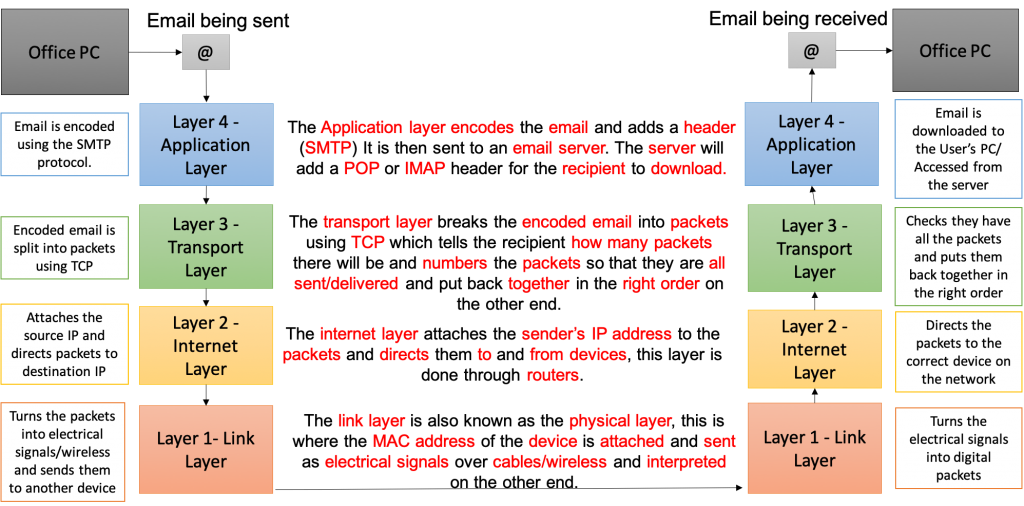
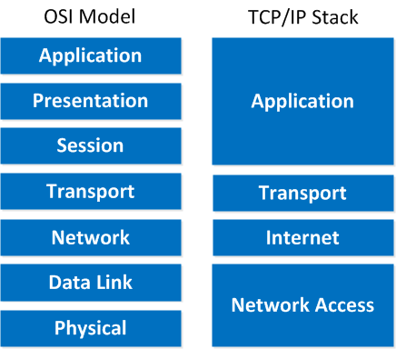
TCP/IP communication is very similar to the OSI model however there are only four layers defined as follows and illustrated below in Figure 2: (a) the application layer, (b) the transport layer, (c) the inter-network or internet layer, and (d) the network access layer.
Generally, data is passed down the stack where it is segmented and encapsulated as PDUs. Communication begins with the application layer passing data to the transport layer where it is encapsulated in a segment. This segment is passed to the internetwork layer where it is encapsulated in a packet. The packet is passed down to the network access layer where it is encapsulated as a frame. Lastly, the frame’s bits are placed on physical transmission media and transmitted. At the destination, the de-capsulation and reconstruction process takes place in the reverse order. It should also be noted that intermediary devices may interact with the data stream at peer levels.
Several texts including the McQuery text (2008) state the TCP/IP network access layer maps to the OSI data link and physical layers. Several texts including the Dye, McDonald, and Rufi text (2005) state that TCP/IP was designed to be hardware independent and therefore only maps to the OSI data link layer leaving no TCP/IP layer to be mapped to the OSI physical layer. This basis provides a clear distinction between a reference model and a protocol model citing the description of the TCP/IP network access layer can best be done by discussing specific implementations (e.g. Ethernet, Serial PPP, etc.). As an example, consider the Ethernet standard divides the Network Access layer into separate Logical Link Control (LLC) and the Media Access Control (MAC) layers. The LLC carries information about the specific network layer protocol (e.g. IPv4 and IPv6) and the MAC provides data link layer physical addressing and delimits the data according to the signaling requirements of medium and data link layer protocol.
One last tidbit
Prof McLaughlin just provided me with one additional easy way to remember the differences between the OSI and TCP/IP models. He stated that in industry, the OSI model is prescriptive whereas the TCP/IP model is descriptive.
Application Layer
Consistent with our reference model and protocol model descriptions above, we can generally define the OSI to TCP/IP mapping by providing protocol examples. At the top-level application layer, most TCP/IP applications include the functionality of OSI layer’s five, six, and seven. As previously cited, the TCP/IP protocol suite developed quicker than the OSI model and this explains some of the differences. Recall the OSI reference model was released in 1984 and the TCP/IP protocol model was well established by this time. TCP/IP also evolved prior to the PC and WWW revolution and therefore prior to the emergence of multiple presentation layer formats. This explains why the TCP/IP application layer comprises the functionality of the more detailed OSI application, presentation, and session layers.
Examples of TCP/IP applications are the Domain Name System (DNS) which resolves Internet names to IP addresses, the Hypertext Transfer Protocol (HTTP) used to manage WWW communications, and the Session Initiation Protocol (SIP) used for IP telephony. It is possible to analyze these protocols and identify specific functionality that would map to the OSI application, presentation, and session layers. As an example from above, recall that the TCP/IP Application Layer SSL/TLS sublayer delivers asymmetric HTTP security for the Transport Layer.
Transport Layer
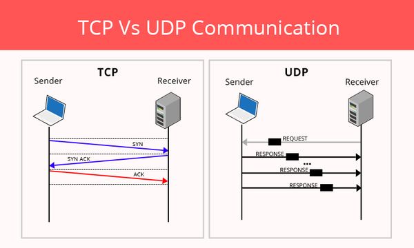
The layer three TCP/IP transport layer (e.g. TCP) maps to the OSI transport layer and manages individual conversations by dividing the application data into smaller pieces and controlling the size and rate of message exchange. As previously introduced, communications have varying data requirements and the TCP/IP model specifies two protocols to accommodate varying requirements. These two protocols are the Transmission Control Protocol (TCP) designed to ensure reliable delivery and the User Datagram Protocol (UDP) designed to provide basic functionality with minimal overhead.
The TCP/IP Transport Layer is responsible for the overall end-to-end transfer of application data by tracking and managing process-level conversations. A conversation is a set of data pieces flowing between source and destination applications. As introduced in previous activities, addressing takes place at three different layers in the OSI and TCP/IP models. From the data source’s perspective, addressing begins at the OSI and TCP/IP transport layer commonly referred to as layer four. In this capacity, the transport layer serves as the link between the application layer and Internet Protocol (IP) layer providing the application layer with access to underlying networking functionality. This is an important layered architecture concept as the transport layer provides the application layer with the transparent transfer of data between end systems without the need to know about the underlying details of the network. We can generally characterize the transport layer’s functionality as (a) managing individual conversations, (b) dividing the application data into smaller pieces called segments or datagrams, and (c) controlling the size and rate of message exchange. This TCP/IP transport layer functionality is commonly referred to as session management, segmentation, and flow control.
As previously introduced, application data can have varying data and network requirements due to the emergence of converged networks that now carry data, voice, and multimedia. Some of this data requires complete reception in order to be valid (e.g. e-mail, business transaction, DBMS data, etc.) while some data can accept minimal losses (e.g. video streaming and VOIP). Some types of data can accept reasonable delays to ensure reliable delivery (e.g. e-mail) whereas some types of data require immediate transfer with minimal latency to be useful (e.g. VOIP). The TCP/IP protocol accommodates all these scenarios through the use of the Transmission Control Protocol (TCP) and the more recent User Datagram Protocol (UDP). TCP ensures reliable delivery through the use of extra control information and processing whereas UDP provides basic functionality with minimal processing and overhead. TCP’s reliable functionality includes properly ordering segments and retransmitting lost or damaged segments. It should be noted that transport layer Protocol Data Units (PDU) are generically referred to as segments however UDP PDUs may also be called datagrams.
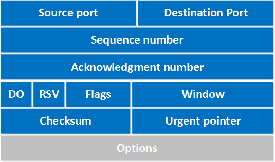
Common to both TCP and UDP are segmentation, encapsulation, and the notion of managing application process-level conversations through the use of port numbers. Both TCP and UDP segment and encapsulate application layer data streams into PDUs and encode 16-bit source and destination ports in the PDU header. Below is the TCP encapsulation segment header.
Port numbers are assigned by the Internet Assigned Numbers Authority (IANA) defined in RFC 1700 (IANA, 2002). Servers have predetermined or well-known ports in the range of 0 – 1023 so that client applications can locate them. The IANA reserved ports 1024 – 49,151 to be assigned to user processes and reserved ports 49,152 – 65,535 to be used as dynamic or private ports. Note that some applications can use both TCP and UDP ports during communications and some TCP and UDP applications have equivalent port numbers (e.g. port 53 is well well-known DNS TCP and UDP common port number). While this will be developed further in future coursework, it should be also noted that client-side ports are often randomly generated and the combination of an IP address plus a port number uniquely identifies an application layer process and is known as a socket.
To provide an overview and illustrate the transport layer’s general functionality, consider the following use-case communications scenario beginning at the source host’s application layer. The source transport layer receives source data streams from the source application layer, segments and encapsulates the data in PDUs, and passes the PDUs to the IP layer for routing. In the opposite direction (i.e. bottom-up at the destination), upon receipt of PDU from the IP layer, the Transport Layer decapsulates and parses the PDU, performs any requisite processing, and passes the data up to the application layer. The encapsulation process involves adding a header to each segment that minimally contains a port or process number that identifies the source and destination application layer processes, the data’s length, and a checksum for verification. This top-level port addressing functionality allows multiple application processes to access networking functionality providing session multiplexing from a single computer or IP address.
Error Detection/Checksum – See Parity Bit from symbolic coding to review error detection.
TCP Functionality
TCP functionality is defined by the Internet Engineering Task Force (IETF) in RFC 793 (IETF, 1981). TCP provides full-duplex, logical connection-oriented functionality that initiates and manages conversations or sessions. TCP also ensures reliable data reception by segmenting and properly reconstituting error-free application data through the use of checksums and sequence and acknowledgment numbers. This orderly reconstitution is necessary citing that IP packets can travel different routes between source and destination and may therefore arrive out of order. In addition to managing the virtual circuits between end devices, TCP sequence, and acknowledgment numbers in conjunction with windowing protocols provide a mechanism to improve overall network throughput by dynamically adapting to network congestion. In summary, TCP provides the following functionality: (a) initiates and manages virtual conversations, (b) tracks individual process-level conversations using source and destination port numbers, (c) segments and encapsulates PDUs, (d) properly reassembles segments into streams of application data, (e) performs flow control by adjusting to network resources in an effort to mitigate segment loss.
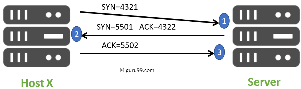
As introduced above, TCP is a connection-oriented protocol and provides the necessary foundation for reliable and transparent application-level communications (e.g. HTTP and SMTP). As a first step, peer TCP layers must establish a connection and this is accomplished through the use of a three-way handshake. To illustrate this session initiation, consider the following example of communicating astronauts who cannot see each other and must verify each other’s existence to establish communications. The first astronaut may state: “Barbara this is Chen, do you read me?”. At this point Chen is seeking to set up a conversation with Barbara however he does not know if she exists or if she can hear him. When Barbara replies, “Chen this is Barbara, I read you loud and clear”, Barbara knows of Tom’s existence and his goal to establish communications however she does not know if he has heard her reply. When Chen replies to Barbara they have now set up a virtual circuit as each astronaut is aware of the other and the conversation can begin. Programmatically, TCP mimics this exchange and establishes a connection by using segment header control data that consists of sequence and acknowledgment numbers and flags described in the pseudo-code example below.
To set up or request a connection, the source TCP layer, (a) sets its synchronize bit (SYN = 1), and (b) sends an initial sequence number. Upon receipt, the destination TCP layer replies to the source by (a) setting its own SYN flag (SYN = 1), (b) setting its acknowledgment flag (ACK = 1), (c) incrementing the source’s sequence number, and moving this number into the reply’s acknowledgment field, and (d) generating its own sequence number, This step introduces TCPs “expectational” communications method as the destination is informing the source of the next transmission it expects to receive through its acknowledgment field. To complete the three-way handshake, the source replies to the destination’s acknowledgment by (a) resetting the SYN flag (SYN = 0), (b) setting its ACK flag (ACK = 1), (c) incrementing the destination’s sequence number and copying it to the source’s acknowledgment number, and (d) increasing its own sequence number. When connection establishment is complete, the peers continue to exchange TCP segments until the connection is terminated through the use of the FIN flag also located in the segment header.
TCP Connection with SYN/ACKs
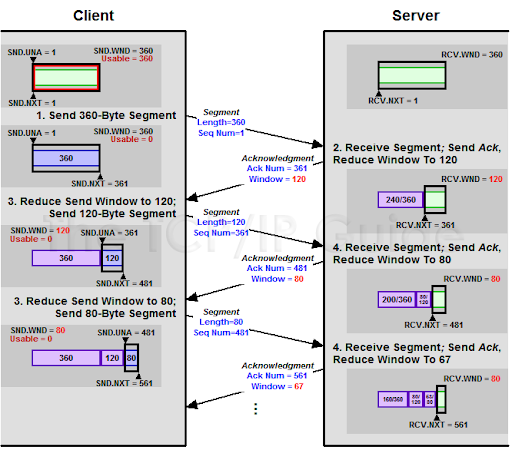
As introduced above, TCP provides reliable communications through the use of segment header sequence and acknowledgment numbers, and error-detecting checksums. In addition to connection setup, expectational sequence, and acknowledgment numbers provide an efficient mechanism to track transmitted data, acknowledge received data, and retransmit unacknowledged data. TCP may also manage flow control and dynamically adapt to network throughput by using a sliding window mechanism based on the sequence and acknowledgment numbers. During connection setup, both parties negotiate the desired window size defined as the number of bytes that can be received without an acknowledgment. This allows the source to send multiple segments before receiving an acknowledgment thereby achieving a logical full duplex connection. A sliding window provides a variable window size that can increase or decrease over the course of a conversation allowing the TCP peers to dynamically adapt to network throughput and congestion. Lost and retransmitted packets are interpreted as network congestion and result in a decrease in the window size. Continuing successful communications are interpreted as a clear communications channel with excess capacity and results in increasing the window size. This elegantly simple, low-overhead mechanism is capable of maximizing throughput with respect to the network’s effective bandwidth and traffic.
TCP Windowing
TCP windowing is expectational equivalent to the 3-way handshake presentation above. To illustrate this, consider a client-server connection where the server is sending 500 segments (numbered 0-499) to a client. The client receives segments 0-399 and 401-499 meaning segment 400 was lost or corrupted somewhere. The client would then send an Ack number 400 that requests the server resend segments 400 and the server would resend segments 400-499 (there would not incur the additional overhead to convey that just segment 400 be resent as it is more efficient for the server to simply resend packets 400-499).
TCP windows will continually adjust based on the client’s buffer capacity and network throughput (bandwidth, congestion, errors, etc.). Below is an example of this dynamic window adjustment.
UDP Functionality
UDP functionality is defined by the IETF in RFC 768 (IETF, 1980). In contrast to TCP, UDP is a connectionless protocol and is used when speed is important and reliability is not an issue (e.g. DNS, VOIP, video streaming, etc.). As a connectionless protocol, UDP-based applications can send information immediately without the need to negotiate the constraints of a conversation or set up a virtual circuit. UDP’s non-guaranteed communications mechanism obviates the need to participate in the three-way handshake necessary to establish the virtual circuit or manage windows and subsequently does not require sequence or acknowledgment numbers.
UDP encapsulates application data in datagrams that contain only minimal control information in an eight-byte header. This minimal header includes source and destination ports, the length of the datagram, and a two-byte checksum. Obviously, UDP’s lack of sequence and acknowledgment numbers, windowing, and flow control render UDP suitable for small amounts of data that do not require segmentation into datagrams. This minimizes transport layer processing time and essentially provides UDP with direct access to the IP layer’s functionality. UDP’s connectionless and unreliable nature requires devices and applications to pre-agree on and understand the datagram’s format and expects application layers to handle sequencing and reliability if required.
Internetwork Layer
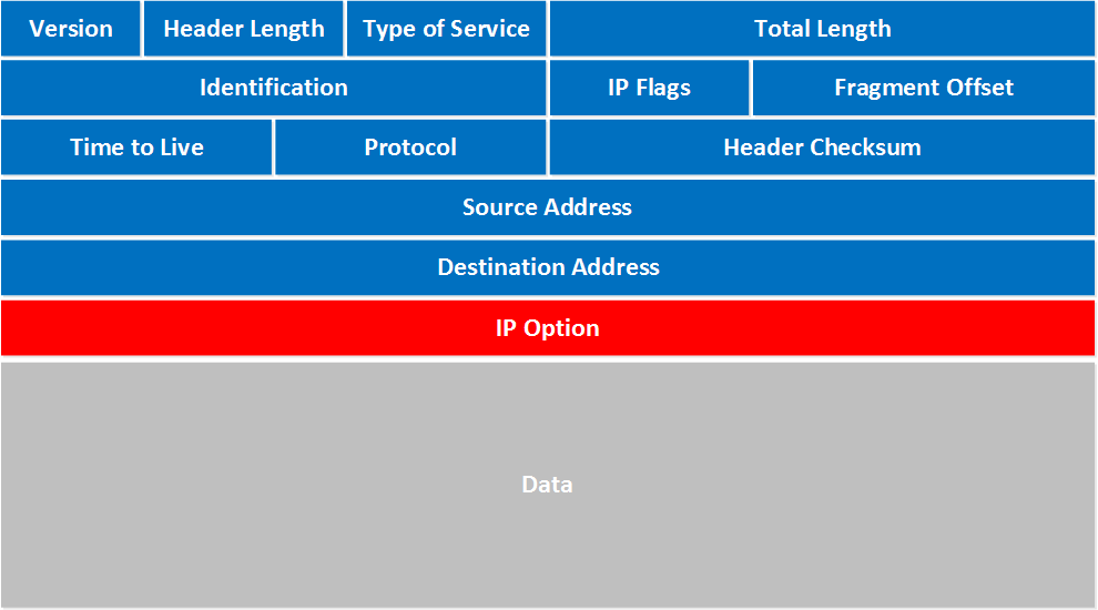
The layer two TCP/IP Inter-network layer (e.g. IP) maps to the OSI network layer and is responsible for formatting transport layer segments as packets, providing source and destination logical addressing, and dynamically routing the packets to their destination. The inter-network layer accomplishes these tasks through the Internet Protocol (IP) of which there are now two variants, IP version four (IPv4) and IP version six (IPv6). Although this will be developed further in future coursework, it is worth noting that a complete logical address is composed of a logical network layer address and a transport layer port number commonly referred to as a socket. Below is the IP packet encapsulation header.
Network Access Layer
Lastly, the network access layer or layer one is the lowest level of the TCP/IP protocol model. Network access functionality is generally responsible for encoding and serializing the frames in a suitable format for transmission and placing the frames on and taking frames off the specific communications medium. Unlike other layers of the TCP/IP suite, the data link layer protocols were not defined by RFC but were developed by organizations to meet the needs of their technologies. As a result, there are conflicting descriptions as to how the layer one TCP/IP network access layer maps to the OSI reference model that may partially be attributed to emergent communications media devices and multi-vendor development
TCP/IP Protocols List
http://www.w3schools.com/tcpip/tcpip_protocols.asp
Summary and Perspective
As previously introduced, network architectures must be designed to appropriately balance the organizational and end device’s needs and these considerations include (a) the speed or data rate, (b) the cost of the components, their installation, and their maintenance, (c) the necessary fault tolerance, (d) the network’s scalability, (e) Quality of Service (QOS), (f) security, and (g) availability. These considerations have a direct correlation with the choice of both the network topology and the use of the appropriate transport layer protocol. It must be strongly asserted that network implementation choices be in concert with an organization’s business goals as Return on Investment (ROI) and Total Cost of Ownership (TCO) are imperative tenets to maintaining a competitive advantage in the present economic climate.
TCP and UDP provide application layer processes and services with transparent communications functionality and they provide software designers with the necessary layered architecture to create flexible and scalable data communications solutions. The transport layer’s port addressing functionality allows multiple application processes to access networking functionality providing session multiplexing from a single computer or IP address. Recall that TCP and UDP differ in that TCP provides reliable, connection-oriented communications whereas UDP provides minimal overhead. This distinction cannot be understated as UDP provides the minimal architecture to essentially achieve direct access to the IP’s best-effort functionality. UDP’s minimal functionality has proven to be critical citing the emergence of converged communications (e.g. VOIP and multimedia streaming). TCP on the other hand provides robust session management necessary for emergent Web Services and Service Oriented Architectures. In summary, TCP and UDP have both proven to be resilient scalable architectures that can support emergent and unforeseen technologies.
References
References
5-4-3 rule (2009). Pcmag.com encyclopedia. Retrieved April 9, 2009, from http://www.pcmag.com/encyclopedia_term/0,2542,t=5-4-3+rule&i=37141,00.asp#
Brown, K., Craig , G., Hester , G., Stinehour, R., Pitt, W. D., Weitzel, M., Amsden, J., Jakab, P. M., & Berg, D. (2003). Enterprise java programming with IBM WebSphere. Boston MA: Pearson Education
Caudle K., & Cannon, K. (2004). CCNA: Guide to Cisco networking (3rd ed.). Boston, MA: Course Technology
Cetron, M. J., & Davies, O. (2008). Trends shaping tomorrow’s world: Forecasts and implications for business, government, and consumers (Part One). The Futurist, 42(2), 35-52.
Comer, D. E. (2000). Internetworking with TCP/IP: Principles, protocols and architectures, (4th ed.). Upper Saddle River, NY: Pearson Publishing.
Dye, M. A., McDonald, R., & Rufi, A. W. (2008). Network fundamentals: CCNA exploration companion guide. Indianapolis, IN: Cisco Press
Erl, T. (2005) Service-oriented architecture: Concepts, technology, and design. Upper Saddle River, NJ: Pearson Education
Friedman, T. L. (2005). The world is flat: A brief history of the 21st century. NY: Farrar, Straus and Giroux
Globalization—Why all the fuss?. (2008). In Britannica Book of the Year, 2001. Retrieved February 13, 2008, from Encyclopedia Britannica Online: http://search.eb.com/eb/article-9344646
Graham, S. Davis, D. Simeonov, S. Daniels, G. Brittenham, P. Nakamura, Y, Fremantle, P. Konig, D., & Zentner, C. (2005). Building Web services with Java (2nd ed.). Indianapolis, IN: Sams Publishing
IANA. (2002). RFC 1700. Retrieved April 13, 2009, from http://www.iana.org/assignments/table-of-contents
IEEE. (1998). IEEE 802.5: LAN/MAN Token-Ring access method. Retrieved April 11, 2009, from http://standards.ieee.org/getieee802/802.5.html
IETF. (1980) RFC 768 User datagram protocol. Retrieved April 11, 2009, http://www.ietf.org/rfc/rfc768.txt
IETF. (1981) RFC 793 Transmission control protocol: DARPA Internet program protocol specification. Retrieved April 11, 2009, from http://www.ietf.org/rfc/rfc0793.txt
Jain, R. (1990). Performance analysis of FDDI token ring networks: effect of parameters and guidelines for setting TTRT. ACM SIGCOMM Computer Communication Review 20(4), 264 – 274.
Johnson, M. J. (1987). Proof that timing requirements of the FDDI Token Ring protocol are satisfied. IEEE Transactions on Communications, 35(6), 275 – 286.
Kamoun, F. (2007). The convergence of business process management and service oriented architecture. Retrieved June 9, 2008 from the Association of Computing Machinery: http://www.acm.org/ubiquity/views/v8i24_bmpsoa.html
Laudon, K. C., & Laudon, J. P. (2004). Management information systems (8th ed.). Upper Saddle River, NY: Pearson Publishing.
McQuerry, S. (2004). CCNA Self-Study: Interconnecting Cisco network devices (INTRO) 640811, 640-801. Indianapolis, IN: Cisco Press
McQuerry, S. (2008). CCNA Self-Study: Introduction to Cisco networking technologies Part 1 (ICND1) 640-822 (2nd ed.). Indianapolis, IN: Cisco Press
Odom, Wendell (2003). CCNA INTRO exam certification guide (CCNA Self-Study, 640-821, 640-801), (1st ed.). Indianapolis, IN: Cisco Press
Pearlson, K. E., & Saunders, C. S. (2006). Managing and using information systems (3rd ed.). Hoboken,NY: Wiley Publishing.
Porter, M. (1985). Competitive advantage: Creating and sustaining superior performance. New York: The Free Press
Rainer, R. K., Turban, E., & Potter, R. E. (2007). Introduction to information systems. Hoboken, NJ: Wiley Publishing.
Ross, F. E. (1989). An overview of FDDI: the fiber distributed data interface. IEEE Journal on Selected Areas in Communications, 7(7), 1043 – 1051.
Satinger, J. W., Jackson, R. B., & Burd, S. D., (2002). Systems analysis and design (2nd ed.). Boston, MA: Course Technology
Shpilberg, D., Berez, S., Puryear, R., & Shah, S. (2007). Avoiding the alignment trap in information technology. MIT Sloan Management Review 49(1).
topology. (2009). In Merriam-Webster Online Dictionary. Retrieved April 3, 2009, from http://www.merriam-webster.com/dictionary/topology
Verity, B. (2003). Guide to networking cabling fundamentals. Boston, MA: Course Technology